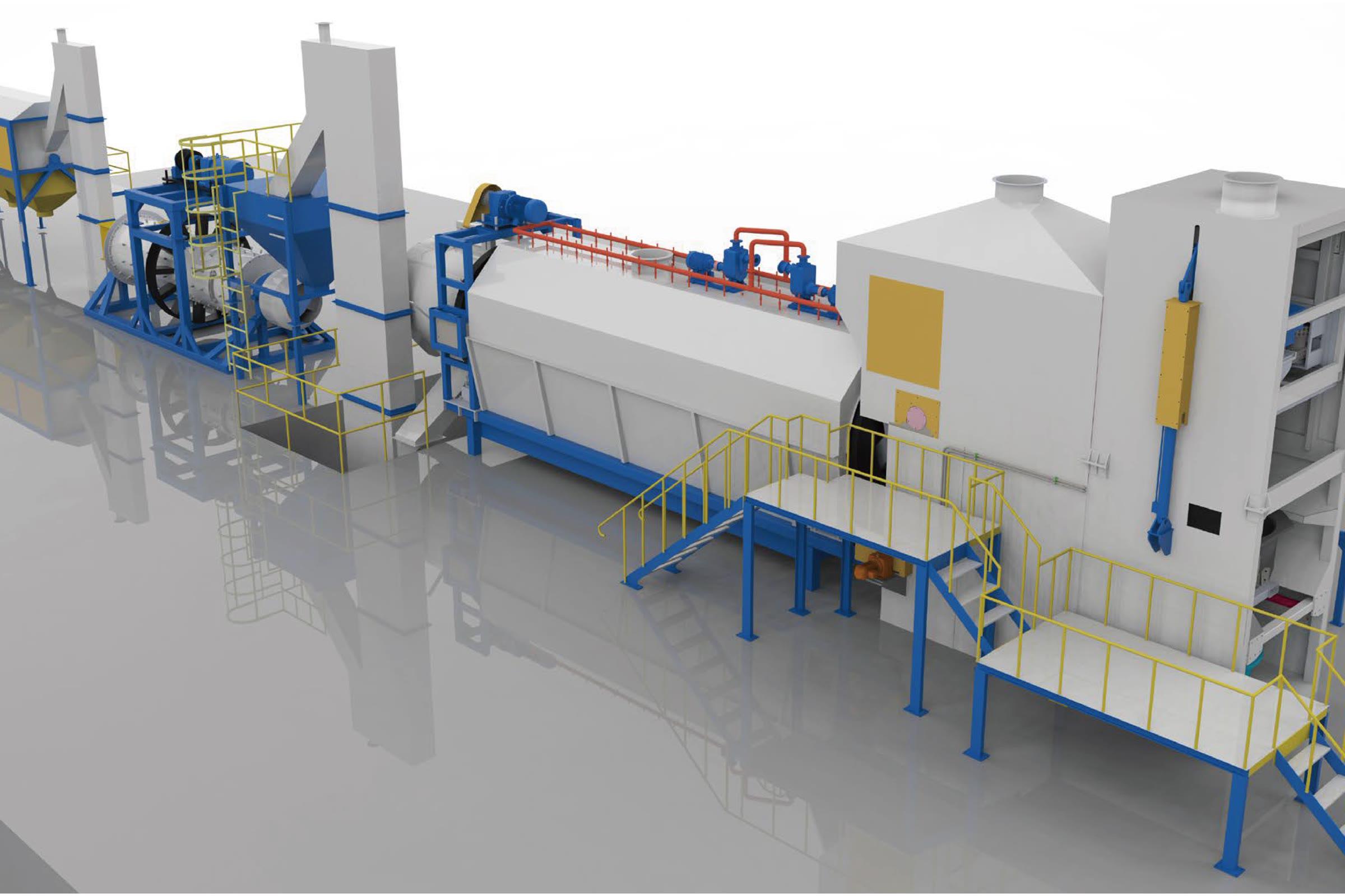
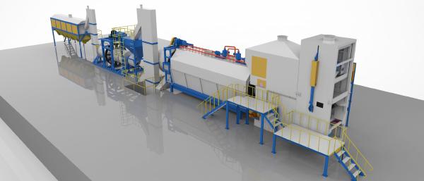
Dross recovery is defined as a connected process. Feed temperature, metallic content, oxidation, transfer time and cooling method influence both metal recovery and the downstream load.
Typical process route # Transfer hot dross from the furnace area. Separate recoverable molten aluminum. Cool residue under controlled conditions. Crush, screen and mill the cooled fraction. Classify, collect and package the output. System modules # For the connected line, see the integrated automatic aluminum dross processing system. Individual modules include:
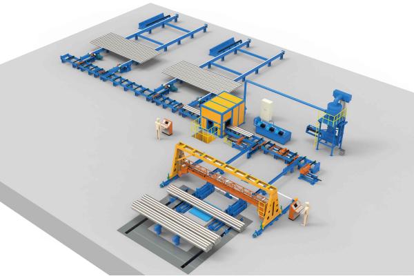
The line is configured around billet alloy, diameter and length range, cut schedule, required throughput and the way finished billets enter homogenizing, extrusion, packing or warehouse logistics.
Typical operating sequence # Store, align and separate incoming billets. Load and feed to the cut position. Saw to the confirmed length schedule. Mark billets and recover generated chips. Convey, sort and stack finished billets. Configurable modules # Compare single-billet and multi-billet sawing systems when defining the line arrangement. Supporting modules include:
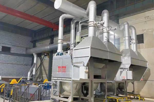
A dust collector is only one part of the system. Capture efficiency begins at the hood and depends on source position, thermal plume, enclosure, capture distance, duct resistance and the number of points operating at the same time.
System path # Capture dust and fumes close to the source. Convey through balanced branch and main ducts. Reduce temperature or settle coarse particles where required. Filter through a pulse-jet baghouse. Discharge, convey and package collected dust. Engineering scope # Hoods and partial enclosures for furnace doors, dross, crushing, screening and sawing points Branch and main duct routing with resistance balancing Gravity settling or temperature-control stages where the process requires them Pulse-jet baghouse, filter media, hopper and rotary discharge equipment Induced-draft fan, compressed air, differential-pressure monitoring and interlocks Maintenance platforms, inspection access and collected-dust handling Design inputs # Dust dataComposition, particle size, concentration, temperature, moisture, explosibility and corrosiveness. Operating pointsSource position, hood arrangement, capture distance and simultaneous operating combinations. System conditionsExisting duct route, available pressure, compressed air, discharge method and maintenance access. Compliance basisProject location, applicable emission limit and agreed acceptance test method. Pre-treatment stage: gravity settling or another pre-separation stage is selected from particle size, concentration, temperature, duct velocity and filter loading. A node value from one project is not used as a product-wide performance statement.
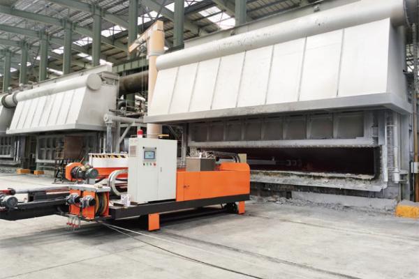
Supporting equipment must match the melt, operating temperature, batch capacity, transfer route and working method. Hengliang Lankang configures these units as part of the casting process and plant logistics.
Supporting scope # Melt treatmentAutomatic refining tanks, wire feeders, online degassing, filtration and process consumables.
Transfer and pouringTransfer ladles, pouring ladles, launders, casting tables and related handling equipment.
Material handlingDross pots, fork pots, grabs, hoppers, electromagnets, charging and maintenance components.